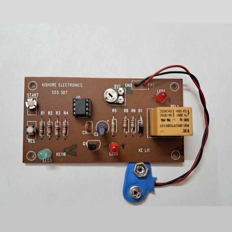
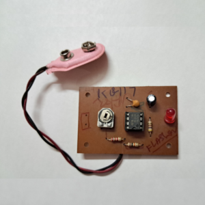
The 555 timer IC is a versatile and widely used component in electronics that can be configured to generate various types of timing signals.
To build a 555 timer with indicator circuit, you’ll need the following components:
- 555 Timer IC: The main component that generates the timing signal.
- Capacitors: Two capacitors are needed to set the timing of the circuit.
- Resistors: Resistors are used to set the values of the timing capacitors.
- LED: An LED is used as an indicator to show the status of the signal.
- Breadboard: A breadboard is used to prototype the circuit.
- Jumper wires: Wires are used to connect the components on the breadboard.
To build the circuit, you’ll need to connect the components as follows:
- Connect pins 2 and 6 of the 555 timer to each other.
- Connect a capacitor between pins 1 and 2 of the 555 timer.
- Connect a second capacitor between pins 2 and 6 of the 555 timer.
- Connect a resistor between pins 6 and 7 of the 555 timer.
- Connect an LED and a resistor in series between pin 3 of the 555 timer and ground.
- Connect power and ground to the breadboard and the 555 timer.
Once the circuit is built, the LED will blink on and off at a frequency determined by the values of the timing capacitors and resistors. This is a simple example of how a 555 timer with indicator circuit can be built. More complex circuits can be built using the 555 timer IC to generate a variety of timing signals for a range of applications.


Reviews
There are no reviews yet.